
A plumbing riser diagram is a schematic vertical-section drawing that maps how a building's plumbing systems route vertically from the utility connection or point of entry up through each floor to the highest fixture or roof termination. It is not drawn to scale and does not show horizontal runs in their true physical positions. What it does show is the logical vertical structure of every pipe stack: sizes, fixture-unit loads, venting, cleanouts, and valve locations, all in one place. Both the Uniform Plumbing Code (UPC) and the International Plumbing Code (IPC) reference riser diagrams as part of permit documentation, and Mysticvalleyservices prepares and reviews them regularly for Massachusetts projects.
The three primary uses of a riser diagram are:
- Permit submittal and plan review: Most U.S. jurisdictions require a riser diagram before issuing a plumbing permit. Plan examiners use it to verify pipe sizing, venting strategy, and fixture-unit calculations.
- Coordination with floor plans and BIM: The riser establishes the vertical logic that floor plans and structural drawings must accommodate. Cross-referencing the two prevents conflicts with beams, slabs, and mechanical systems.
- Maintenance and troubleshooting: Technicians rely on risers to trace valve locations, cleanout access points, and backflow devices relative to specific floors and branches.
Table of Contents
- What does a riser diagram need to show?
- How do you read a riser diagram?
- When are riser diagrams required, and what do reviewers check?
- How do you create a permit-ready riser diagram?
- Common mistakes that cause permit delays
- What do good riser diagrams look like in practice?
- Key Takeaways
- Why the riser diagram is the most underestimated document in a permit package
- Mysticvalleyservices can help you get your riser right
- Useful sources and further reading
What does a riser diagram need to show?
A complete riser diagram covers every system from its point of connection to its termination point, whether that is a roof vent stack or a utility tie-in at grade. Plan reviewers check for specific items, and missing even one can trigger a resubmittal.
Required components:
- Utility connection or point of entry (water meter, building drain tie-in, gas meter where applicable)
- Vertical risers for each system: domestic cold water, hot water, sanitary waste and vent (DWV), storm drainage, and gas or nonpotable water where the scope includes them
- Branch connections at each floor, with fixture types noted
- Pipe sizes at every segment, including size reductions at branches
- Fixture-unit loads per floor and cumulative totals
- Vent stacks and individual vents, with roof termination heights
- Cleanout locations (at base of stack, at direction changes, and per code spacing requirements)
- Trap locations for each fixture
- Isolation valves, pressure-reducing valves, and zone boundaries
- Backflow prevention devices where required (typically on irrigation, fire suppression tie-ins, and commercial connections)
Drafting conventions follow a consistent logic across most U.S. jurisdictions. Risers are drawn schematically in single-line format: one line represents one pipe, regardless of diameter. Floor bands (horizontal lines labeled with floor designations) divide the drawing vertically. Pipe sizes use a circled leader notation, where a small circle sits on the pipe line and an arrow points to the inner-diameter callout. Omitting those circled leaders is one of the most common reasons a permit gets kicked back.
Annotations should also call out pipe material (copper, PVC, cast iron), slope for horizontal runs where shown, and fixture-unit totals per floor in a summary table. When the scope includes both a supply diagram and a DWV diagram, they are often drawn as two separate sheets rather than combined on one crowded drawing.

How do you read a riser diagram?
Reading a riser diagram starts with understanding what it is not. It is schematic, not spatial. The vertical distances between floors are representative, not measured. Horizontal branches are shown as short stubs off the main stack, not as true-length runs. Once you accept that, the drawing becomes straightforward to follow.
Single-line vs. isometric vs. floor plan:
| Drawing type | What it shows | Best used for |
|---|---|---|
| Single-line riser | Vertical logic, pipe sizes, fixture loads, venting | Permit submittal, plan review |
| Isometric (axonometric) | 3D projection of pipe routing | Contractor coordination, fabrication |
| Floor plan | Horizontal branch layout, fixture locations | Spatial coordination, rough-in |
The Fairfax County technical bulletin makes this distinction explicit: single-line risers are required for plan acceptance, and submitting only an isometric can delay review. Some jurisdictions accept isometrics as a supplement, but the single-line schematic is the baseline document.
Symbol primer for reading a riser:
- Vertical pipe runs: solid or dashed lines running top to bottom (dashed often indicates concealed or future)
- Circled leaders: pipe size callouts on each segment
- Trap symbols: U-shaped or P-shaped notation at each fixture connection
- Cleanout symbols: a small circle with "C.O." label
- Vent terminator: a line extending above the roof band, sometimes with a cap symbol
- Flow direction: arrows on waste lines pointing toward the building drain
- Floor bands: horizontal lines labeled "1st Floor," "2nd Floor," etc., dividing the vertical drawing into zones
When you use a riser alongside a floor plan, the floor plan tells you where a fixture sits in the room; the riser tells you what size pipe feeds it, how it drains, and how it vents. Neither drawing is complete without the other. Using a riser as an installation map, treating its stub-out positions as exact coordinates, is a frequent source of conflicts with structural framing. For a deeper look at how venting systems affect riser design, the principles of air admittance and stack venting directly shape what your riser diagram must show.
When are riser diagrams required, and what do reviewers check?
Riser diagrams are mandatory for plumbing permit applications in most U.S. jurisdictions. The UPC and IPC both require permit documentation to demonstrate that pipe sizing, venting, and drainage design comply with code. The riser diagram is the primary document plan examiners use to make that determination.
Seattle's plumbing code, Section 107.7.5, is a useful local example: it requires riser diagrams to show all plumbing systems from the utility connection to the furthest fixture or roof termination, with pipe sizes, fixture-unit loads, and vent terminations clearly labeled. Most jurisdictions follow similar logic, even when the specific code section differs.
Plan examiners focus on friction loss logic, venting efficacy, and pipe sizing. A diagram that clearly lists fixture-unit totals per floor short-circuits many review questions and keeps the approval moving.
Permit reviewer checklist:
- Utility connection shown (water meter, building drain, gas meter)
- Fixture-unit calculations present and totaled per floor
- Pipe sizes called out at every branch and size change
- Venting shown for every fixture group, with roof termination heights
- Cleanouts at stack base, horizontal offsets, and per-code spacing
- Valve locations (isolation, pressure-reducing, zone)
- Backflow prevention devices where required
- Legend and general notes included
- Annotations legible (circled pipe-size leaders, material callouts)
- Drawing matches floor plan fixture locations
Incomplete diagrams frequently cause project delays. A clean, complete set typically moves through first-review faster than one that requires a correction letter. For property owners and contractors who want to understand the code compliance side in more depth, Mysticvalleyservices has a resource on plumbing code compliance that covers common permit issues.
How do you create a permit-ready riser diagram?
The tools most commonly used are Autodesk Revit (Revit MEP), AutoCAD or AutoCAD MEP, and hand-drafted single-line sketches for early-stage submittals. PDF and DWG are the standard export formats for permit packages; check your local building department for specific file requirements.
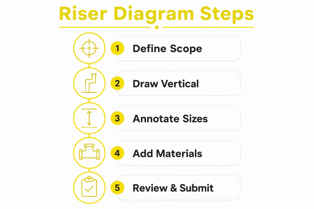
Step-by-step workflow:
- Define scope and stack zones. Identify which systems are in scope (domestic water, DWV, storm, gas) and map the vertical stack locations against the floor plan.
- Collect fixture-unit calculations. Pull fixture-unit values from UPC or IPC tables for every fixture on each floor. Total them per floor and cumulatively.
- Draw the schematic riser. Use single-line format with floor bands. Start at the utility connection and work upward. Show each branch stub with a fixture label.
- Annotate pipe sizes, cleanouts, valves, and vent terminations. Use circled leaders for every pipe segment. Mark cleanout locations and valve types explicitly.
- Add legend, general notes, and material callouts. Include a fixture-unit summary table by floor. Note pipe materials and any special conditions (insulation, fire-rated penetrations).
- Cross-reference against floor plans. Confirm that every fixture on the floor plan appears on the riser and that stack locations do not conflict with structural members.
- Prepare the submittal package. Compile the riser, floor plans, fixture-unit calculations, and material specs into a single PDF set with a cover sheet and contact information.
Revit MEP notes: In Revit, the most practical approach is to create a dedicated view with floor levels visible and all unrelated worksets turned off. This produces a clean, riser-like view you can export as a simplified single-line PDF. Where the jurisdiction accepts isometrics as a supplement, export a 3D view for contractor coordination, but always confirm the local plan-review preference before submitting only the 3D output.
Pro Tip: Add a floor-by-floor fixture-unit summary table directly on the riser sheet. Plan examiners can verify your sizing logic without flipping between sheets, and that alone can cut first-review questions in half.
Common mistakes that cause permit delays
Even experienced drafters miss items that reviewers catch immediately. The most frequent errors are not complex; they are omissions.
Common drafting errors:
- Missing pipe-size callouts on one or more segments (the single most common rejection reason)
- Treating the riser as a to-scale installation map rather than a schematic
- Omitting cleanouts at the base of stacks or at horizontal offsets
- Missing vent terminations or showing vents that do not reach above the roof line
- No fixture-unit totals, or totals that do not match the floor plan fixture count
- Unclear or absent legend (reviewers should not have to guess what a symbol means)
- Incorrect symbol usage (using an isometric convention on a single-line drawing)
Permit submittal checklist:
- Riser diagram (single-line, all systems in scope)
- Floor plans showing horizontal branch layout and fixture locations
- Fixture-unit calculations with per-floor and cumulative totals
- Legend and general notes sheet
- Material specifications (pipe type, fitting standards)
- Designer or contractor contact information and license number
On timeline: a complete, clean submittal typically clears first review faster than an incomplete one that requires a correction letter and a resubmittal cycle. Administrative resubmittal fees vary by jurisdiction, but the real cost is schedule. A two-week review delay on a commercial project can push a construction start by a month.
Updating risers during construction: Use revision clouds to mark changed areas, maintain a revision table with dates and descriptions, and export date-stamped PDFs. Keep the riser and floor-plan revisions in sync; an inspector who finds a mismatch between the two will stop work until the discrepancy is resolved. For guidance on managing as-built documentation through construction, Mysticvalleyservices covers version control practices in detail.
What do good riser diagrams look like in practice?
Two brief examples show how annotation choices affect both permit review and field coordination.
Residential stack: single-family home
A typical two-story single-family riser shows one DWV stack serving a first-floor bathroom, a second-floor bathroom, and a kitchen. Key annotations:
- Pipe size change at the second-floor branch: The stack drops from 3-inch to 4-inch at the base to handle the combined fixture-unit load. Calling this out explicitly prevents a reviewer from questioning whether the sizing was calculated.
- Individual vents vs. wet venting: Showing which fixtures are wet-vented and which have individual vents tells the reviewer the venting strategy without requiring a separate narrative.
- Cleanout at stack base: Marked with "C.O." and an arrow indicating access direction. Reviewers look for this immediately on residential submittals.
For a homeowner preparing a permit package, the home plumbing maintenance checklist from Mysticvalleyservices is a useful companion for understanding what a complete system should include.
Commercial stack: multi-story office building
A five-story office building riser is more complex but follows the same logic. Notable elements:
- Fixture-unit summary table by floor: Each floor lists the fixture count, unit value, and cumulative total. A plan examiner can verify pipe sizing at a glance without doing the math independently.
- Zone isolation valves: Shown at each floor branch on the domestic water riser, with valve type noted. This matters for maintenance: a technician can isolate one floor without shutting down the building.
- Backflow preventer at the domestic water entry: Required by most jurisdictions for commercial connections. Its location on the riser tells the inspector it is present and accessible.
On a recent commercial project, catching a missing cleanout on the riser drawing before submittal saved a correction letter and kept the permit review on schedule. That one annotation, added in ten minutes, prevented a two-week delay.
For commercial property managers, Mysticvalleyservices has a dedicated resource on commercial plumbing risers that goes deeper on multi-story coordination.
When presenting an annotated diagram in a submittal, include a legend on the same sheet, a "not to scale" note, and the designer's contact information and license number. Reviewers should not have to search a separate sheet for symbol definitions.
Key Takeaways
A plumbing riser diagram is a schematic vertical drawing that shows pipe sizes, fixture-unit loads, venting, and cleanouts for every system from utility connection to roof termination, and it is the primary document plan examiners use to approve a plumbing permit.
| Point | Details |
|---|---|
| Definition | A schematic vertical-section drawing showing vertical routing, pipe sizes, fixture loads, and venting for all plumbing systems. |
| Permit requirement | Most U.S. jurisdictions require a riser diagram for permit approval; UPC and IPC both reference it as core documentation. |
| Single-line format | Submit a single-line schematic for plan review; isometrics are supplements, not replacements, per Fairfax County guidance. |
| Top drafting priority | Include circled pipe-size leaders on every segment and a floor-by-floor fixture-unit summary table to prevent reviewer questions. |
| Mysticvalleyservices | Mysticvalleyservices prepares, reviews, and coordinates permit-ready riser diagrams for Massachusetts residential and commercial projects. |
Why the riser diagram is the most underestimated document in a permit package
Most contractors treat the riser as a formality, something to produce quickly so the permit application is complete. That is the wrong frame. The riser is the only document in a typical permit package that shows the entire vertical logic of a plumbing system on one sheet. A plan examiner who cannot follow the venting strategy or verify the fixture-unit math from the riser alone will write a correction letter. Every correction letter costs time.
What gets missed in most guides is how much the riser matters after the permit is issued. A well-annotated riser with valve locations, cleanout access points, and zone boundaries becomes a maintenance reference that a building owner can hand to any plumber, years later, without needing to trace pipes through walls. The preventive maintenance value of a complete riser is real and underused.
The other thing worth saying: the riser is not the installation drawing. Contractors who scale off a riser to set rough-in dimensions will get into trouble with structural framing. The riser tells you what the system does vertically. The floor plan tells you where. You need both, and neither replaces the other.
Mysticvalleyservices can help you get your riser right
Getting a riser diagram wrong is one of the most avoidable reasons a permit application stalls. Mysticvalleyservices works with Massachusetts homeowners, contractors, and property managers to prepare permit-ready plumbing documentation, including riser diagrams, fixture-unit calculations, and full submittal packages. The difference between a clean first-review approval and a correction-letter cycle often comes down to whether the riser was prepared by someone who knows what plan examiners actually look for.

Whether you are pulling a permit for a bathroom remodel, a new commercial build-out, or a full system replacement, Mysticvalleyservices handles the drafting, the code cross-check, and the submittal coordination. View our services to see how we support permit applications from first draft to approved set, and reach out to get your project moving.
Useful sources and further reading
The following references informed this guide. Always verify current requirements with your local building department, as code adoption and local amendments vary by jurisdiction.
- UPC/IPC riser diagram requirements (UPCodes): primary reference for permit documentation requirements under the Uniform Plumbing Code.
- Fairfax County Technical Bulletin 19-07: Single-Line Plumbing Riser Diagrams: jurisdiction-specific guidance on single-line vs. isometric requirements and plan acceptance standards.
- DrawPlumbingPlans.com: A Riser Diagram Gets You a Permit: practical guidance on notation conventions, circled pipe-size leaders, and permit review expectations.
- Budlong.com: How to Read and Prepare a Plumbing Riser Diagram: technical guide covering schematic conventions and cross-referencing with floor plans.
- Helonic: How to Read Plumbing Riser Diagrams: overview of required diagram elements and maintenance applications.
- Mysticvalleyservices: Plumbing Code Compliance Issues: guidance on avoiding common permit rejections in Massachusetts.
- Mysticvalleyservices: Commercial Plumbing Riser Guide: deeper coverage of multi-story riser coordination for commercial properties.
For jurisdictional specifics, contact your local building or plumbing authority directly. Code adoption varies: some Massachusetts municipalities follow the Massachusetts State Plumbing Code, which references IPC with local amendments, while others maintain additional local requirements.
This article is general technical information, not legal or engineering advice. Confirm current permit requirements and code sections with your local authority having jurisdiction (AHJ) or a licensed plumbing engineer for your specific project.