
Plumbing load calculation estimates a building's peak probable water demand by converting each fixture's water use into standardized fixture units, then applying probability theory to predict how many fixtures will run at the same time. The result tells engineers and plumbers exactly how large each pipe segment needs to be. Get it wrong and you end up with either undersized pipes that starve fixtures of pressure or oversized pipes that waste money and let water stagnate. The two governing model codes in the United States are the International Plumbing Code (IPC) and the Uniform Plumbing Code (UPC), and both require sizing calculations that account for all of the following:
- Fixture unit load on each pipe segment
- Minimum available pressure from the water main or pressure tank
- Pressure losses from elevation changes between the main and the controlling fixture
- Friction losses through pipe length, fittings, valves, water heaters, and backflow preventers
- Minimum flow pressure required at the most remote fixture
Table of Contents
- How plumbing load calculation works: the fixture unit concept
- Translating fixture units into pipe size: flow, pressure, and friction loss
- Why water conservation is changing how loads get calculated
- Practical implications for homeowners and property managers
- Step-by-step procedure to perform a plumbing load calculation
- Residential vs. commercial load calculation examples
- How simultaneous usage and demand factors shape the final load
- Tools and software used for plumbing load calculations
- Key Takeaways
How plumbing load calculation works: the fixture unit concept
The fixture unit system is the foundation of every plumbing load calculation. Roy B. Hunter developed it in the 1940s and published it through the National Bureau of Standards. His core insight was simple: not all fixtures run at the same time, so designing for full simultaneous flow wastes pipe capacity and money.
Each fixture gets a dimensionless weight called a water supply fixture unit (WSFU) based on its flow rate, how long it runs per use, and how often it is used. Under the IPC, a bathroom sink carries 1 WSFU, a bathtub or shower 2 WSFU, and a toilet 2.5 WSFU. Hunter then applied the binomial distribution to predict how many fixtures out of a total group would be running at any given moment. In a building with 20 flush valves and 20 flush tanks, probability of simultaneous use of more than 3 flush valves and 8 flush tanks at the same instant is less than 1%.
Key points about fixture units:
- Fixture units are dimensionless; they are not gallons per minute
- Hot and cold systems are sized separately, each typically taking ¾ of the total fixture unit count
- The fixture unit method applies to both residential and commercial demand
- Continuous-use fixtures like hose bibs must be added as direct gpm values, not fixture units
Translating fixture units into pipe size: flow, pressure, and friction loss
Once you total the fixture units for a pipe segment, you convert them to gallons per minute using Hunter's Curve or a code table. This conversion is deliberately non-linear. 1,000 fixture units equal 208 gpm, but 2,000 fixture units equal only 321 gpm, not 416. The curve flattens because the probability of simultaneous use drops as the fixture count grows.
Flow rate alone does not determine pipe size. You also have to verify that pressure survives the trip from the water main to the farthest fixture. Pipe sizing must account for pressure losses from elevation, fittings, and friction at every step. A common shortcut: multiply the actual developed pipe length by 1.5 to estimate the equivalent length including fittings and valves, then calculate friction loss from that figure.
Flow velocity is the third constraint. Pipe velocity must stay at or below 8 feet per second to prevent erosion, noise, and water hammer. A pipe that handles the flow rate on paper but pushes water at 12 ft/s will fail early and loudly.
Pro Tip: Start your pressure calculation at the water main and subtract every loss in sequence: elevation gain, meter loss, friction through the service line, and friction through the distribution system. The number left over must meet or exceed the minimum pressure required at the controlling fixture, typically 15–20 PSI.
Critical factors in pipe sizing:
- Total fixture unit load on each segment
- Available pressure at the source
- Elevation difference between source and controlling fixture
- Friction loss through pipe length, fittings, and equipment
- Maximum flow velocity (8 ft/s limit per IPC Appendix E)
- Minimum residual pressure at the most remote fixture
Why water conservation is changing how loads get calculated
Hunter's Curve was built on fixture flow data from the 1940s. Modern low-flow toilets, WaterSense faucets, and high-efficiency appliances use far less water per cycle than their mid-century counterparts. The result: the traditional WSFU method can significantly overestimate peak demand in multifamily buildings equipped with low-flow fixtures. Pipes sized on those inflated numbers are far larger than needed, which raises installation costs and creates long water dwell times that degrade water quality.
The IAPMO Water Demand Calculator (WDC), now codified in UPC Appendix M, addresses this directly. It uses empirical data from modern residential end-use surveys and applies updated probability formulas to predict peak demand more accurately. The WDC is available as a free Excel download from IAPMO and is the first major peer-reviewed update to residential peak demand sizing in over 80 years.
Benefits of right-sizing with the WDC:
- Smaller pipe diameters reduce material and installation costs
- Smaller water service entrance means a smaller meter and lower connection fees
- Reduced pipe volume shortens hot water delivery time, cutting energy waste
- Less water sitting in oversized pipes means lower risk of bacterial growth
Practical implications for homeowners and property managers
Accurate load calculations protect your investment in two concrete ways: they prevent the system from being built wrong in the first place, and they keep you on the right side of plumbing code compliance during inspections. A permit office reviewing your construction documents wants to see that your water service line and meter can deliver the calculated demand at minimum pressure to the farthest fixture.
For property managers overseeing multi-unit buildings, the stakes are higher. Oversized pipes in a low-flow building are not just wasteful; they create stagnation zones where water sits warm long enough to raise Legionella risk. Undersized pipes cause pressure complaints from tenants and accelerate fixture wear.
Practical steps when approaching a plumbing project:
- Inventory every fixture and assign IPC or UPC fixture unit values before design begins
- Confirm the available pressure at the water main with your utility before sizing the service line
- Use the IAPMO WDC for residential new construction or renovation with low-flow fixtures
- Verify that your licensed plumber checks velocity limits, not just flow capacity, on every segment
- Pull permits and have the system inspected; a passed inspection is documented proof of compliance
Step-by-step procedure to perform a plumbing load calculation
A complete plumbing system load estimation follows a logical sequence that mirrors the IPC Appendix E segmented loss method.
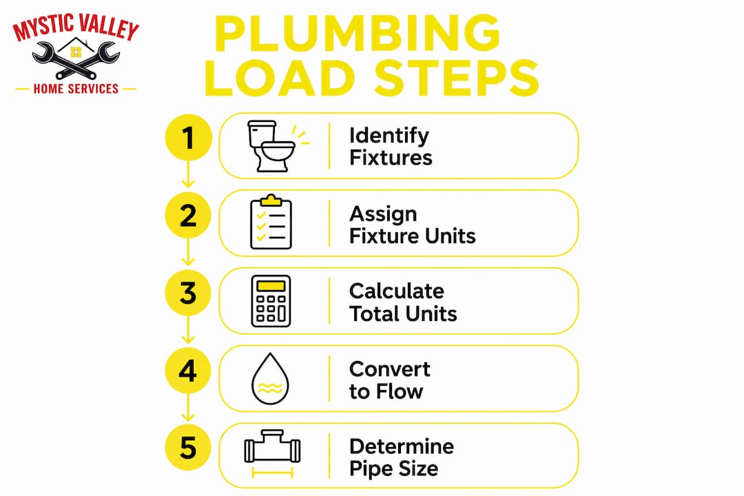
- List every fixture in the building and assign its WSFU value from the applicable code table.
- Separate hot and cold loads. Use ¾ of total fixture units for each branch; add continuous-use fixtures as direct gpm.
- Total fixture units per pipe segment, working from the most remote fixture back toward the main.
- Convert fixture units to gpm using Hunter's Curve or the WDC for low-flow residential systems.
- Determine available pressure at the building control valve after subtracting elevation loss and meter loss.
- Calculate equivalent pipe length by multiplying developed length by 1.5 to account for fittings and valves.
- Calculate allowable friction loss per 100 feet by dividing remaining pressure by equivalent length, then multiplying by 100.
- Select pipe diameter from code charts using gpm demand, allowable friction loss, and velocity limit.
- Verify minimum pressure at the controlling fixture after all losses; resize if the result falls below 15–20 PSI.
Residential vs. commercial load calculation examples
A single-family home with one bathroom, a kitchen, and a clothes washer carries roughly 6 indoor fixtures. Running those through the IAPMO WDC yields a whole-house peak demand around 9 gpm, a number that typically supports a ¾-inch service line. The calculation is straightforward because fixture counts are low and simultaneous use is easy to bound.

A 20-unit apartment building is a different problem. Each unit might carry 8–10 fixtures, giving a building total well above 100 WSFU. Under the traditional WSFU method, that total could push the service line to 2 inches or larger. The WDC, calibrated on actual multifamily flow data, often yields a meaningfully smaller result because it reflects how residents actually use water across a building rather than assuming worst-case stacking. For multi-unit building plumbing, that difference in pipe diameter translates directly to lower construction cost and better water quality.
Commercial buildings add another layer: process loads, kitchen equipment, and fire suppression systems that run continuously and must be added as direct gpm values outside the fixture unit framework. The American Water Works Association fixture value method, published in its M22 Manual, is sometimes used for sizing water service lines in commercial settings using measured meter data, though it is not referenced in major U.S. plumbing codes for branch piping.
How simultaneous usage and demand factors shape the final load
The entire fixture unit system rests on one idea: the more fixtures a building has, the smaller the fraction that will run at the same time. Hunter encoded this in the binomial distribution, designing to the 99th percentile of simultaneous use. That means the system is sized to handle a demand level that will be exceeded less than 1% of the time.
Demand factors adjust the raw fixture unit total downward when usage patterns are predictably low. A private office bathroom used by two people has a very different simultaneous-use profile than a public restroom serving a stadium. Codes and engineers apply these factors to avoid building a system sized for a peak that will never occur in practice. The non-linear shape of Hunter's Curve already captures much of this effect, but building type, occupancy schedule, and fixture mix all influence where on that curve a given project lands.
Tools and software used for plumbing load calculations
The IAPMO Water Demand Calculator is the most current peer-reviewed tool for residential sizing and is available free at iapmo.org. It runs in Microsoft Excel, requires no special license, and outputs peak demand in gpm directly, skipping the fixture-unit-to-gpm conversion step.
For IPC-based projects, engineers typically work from the code's own Appendix E tables and friction loss charts, sometimes supported by general-purpose mechanical engineering software that includes pipe sizing modules. Online fixture unit calculators can help homeowners and property managers do a quick sanity check on fixture counts before meeting with a licensed plumber, though they are not a substitute for a full engineered calculation on permitted work.
Mysticvalleyservices handles plumbing load calculations, pipe sizing, and code compliance for homeowners and property managers across Massachusetts. Whether you are planning a new build, adding fixtures to an existing system, or trying to understand why pressure is dropping in your building, the team at Mystic Valley Home Services can walk you through the numbers and get your system sized right the first time. Learn more about code compliance requirements or explore the full range of plumbing and heating services available in your area.

Key Takeaways
Plumbing load calculation converts fixture units into peak probable flow using probability theory, then sizes pipes to deliver that flow at adequate pressure to the most remote fixture.
| Point | Details |
|---|---|
| Fixture units drive sizing | Each fixture gets a WSFU value; totals convert to gpm via Hunter's Curve or the IAPMO WDC. |
| Conversion is non-linear | 1,000 fixture units equal 208 gpm, but 2,000 units equal only 321 gpm, reflecting probability. |
| Velocity caps protect pipes | Flow must stay at or below 8 ft/s to prevent erosion, noise, and premature pipe failure. |
| Old methods oversize modern buildings | The WSFU method can significantly overestimate peak demand in low-flow multifamily buildings. |
| Pressure must survive every loss | Available pressure minus elevation, meter, and friction losses must still meet 15–20 PSI at the farthest fixture. |